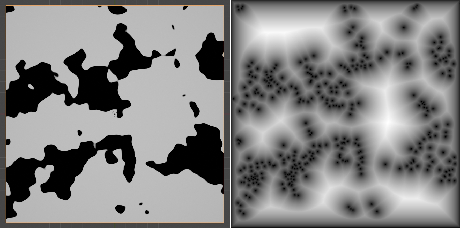
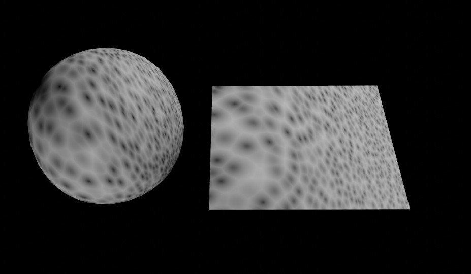
Is there a way to use another texture (like noise, second voronoi, musgrave, etc…) for controlling voronoi distibution of cells in such a way that one value gives densly packed cells and no value gives mostly empty space? First picture is a noise texture, second one is a mockup what I want to achieve.
I’m trying to step up my shading game, so if there is a way that involves some basic math, I’d be glad for any tip what kind of operation and on what nodes could give that result.
I really miss better tools for blending generic textures and shaders in a procedural way. Creating belivable masks between two different patterns is not very straightforward in Blender.
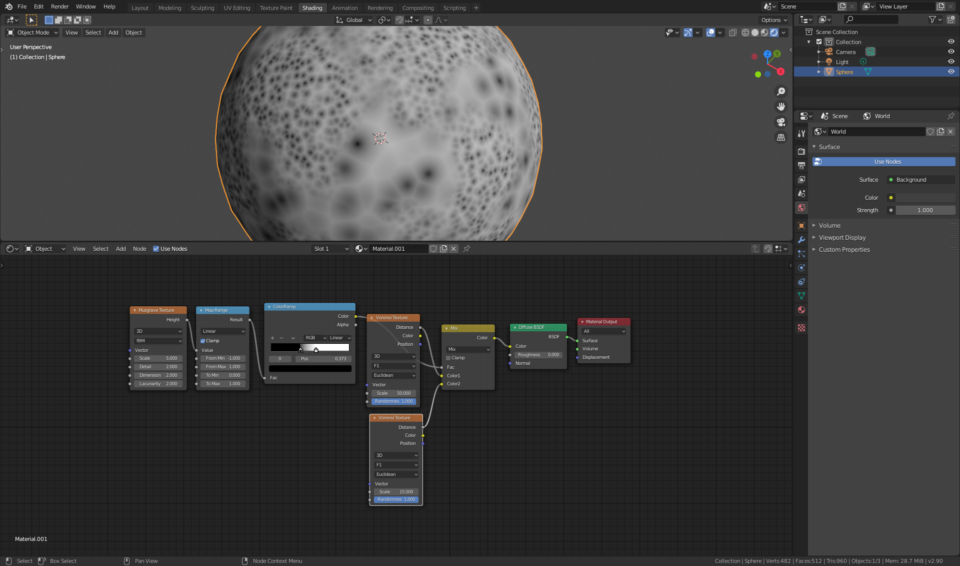
I am also interested so I’m going to play around with it starting wit the mapping. Voroni is calculated from a random distribution of points, so if you want to control the jittering effect like this, then the distribution of points prior to coloring needs to be controlled after which the algorithm colors them based on their closest distances from each other.
Unfortunately, I think the main issue is that the voronoi node in Blender simply doesn’t have density control. Not sure if there’s an acceptable workaround for this
I also tried and failed to achieve this size-varying voronoi, wondering if it can be done with math nodes or only with a modified voronoi on Blender side. Hmm.
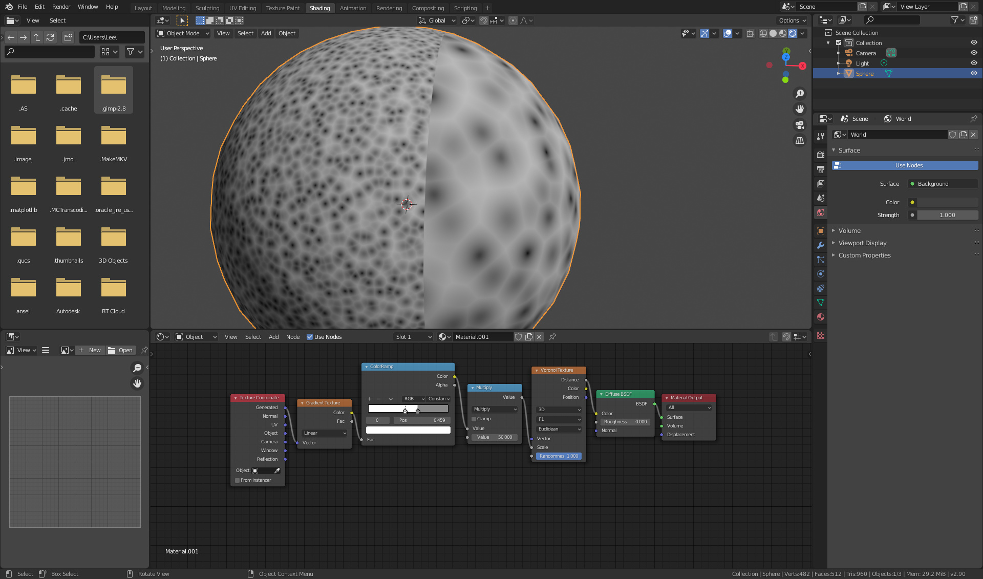
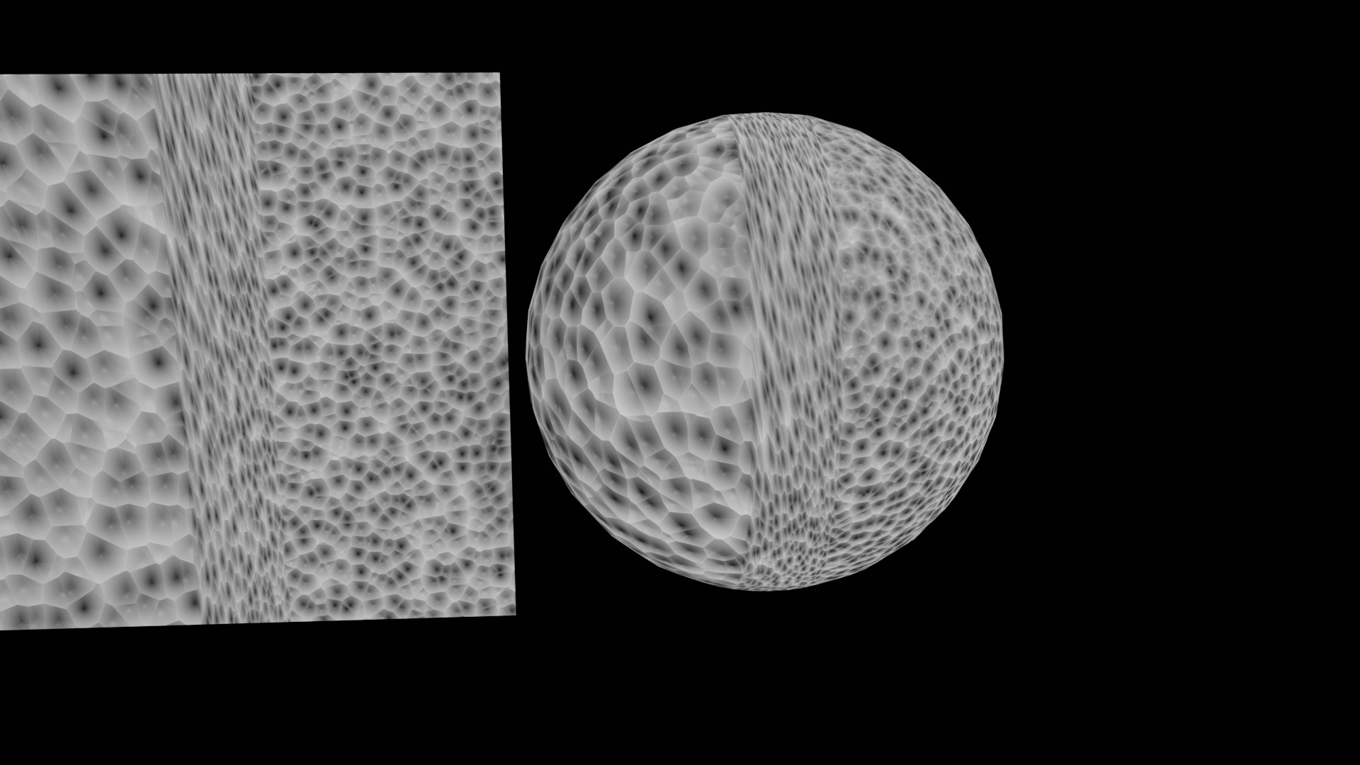
It’s actually quite weird. It should work based on the scale - but it goes screwy when you have a phased transition between two colours.
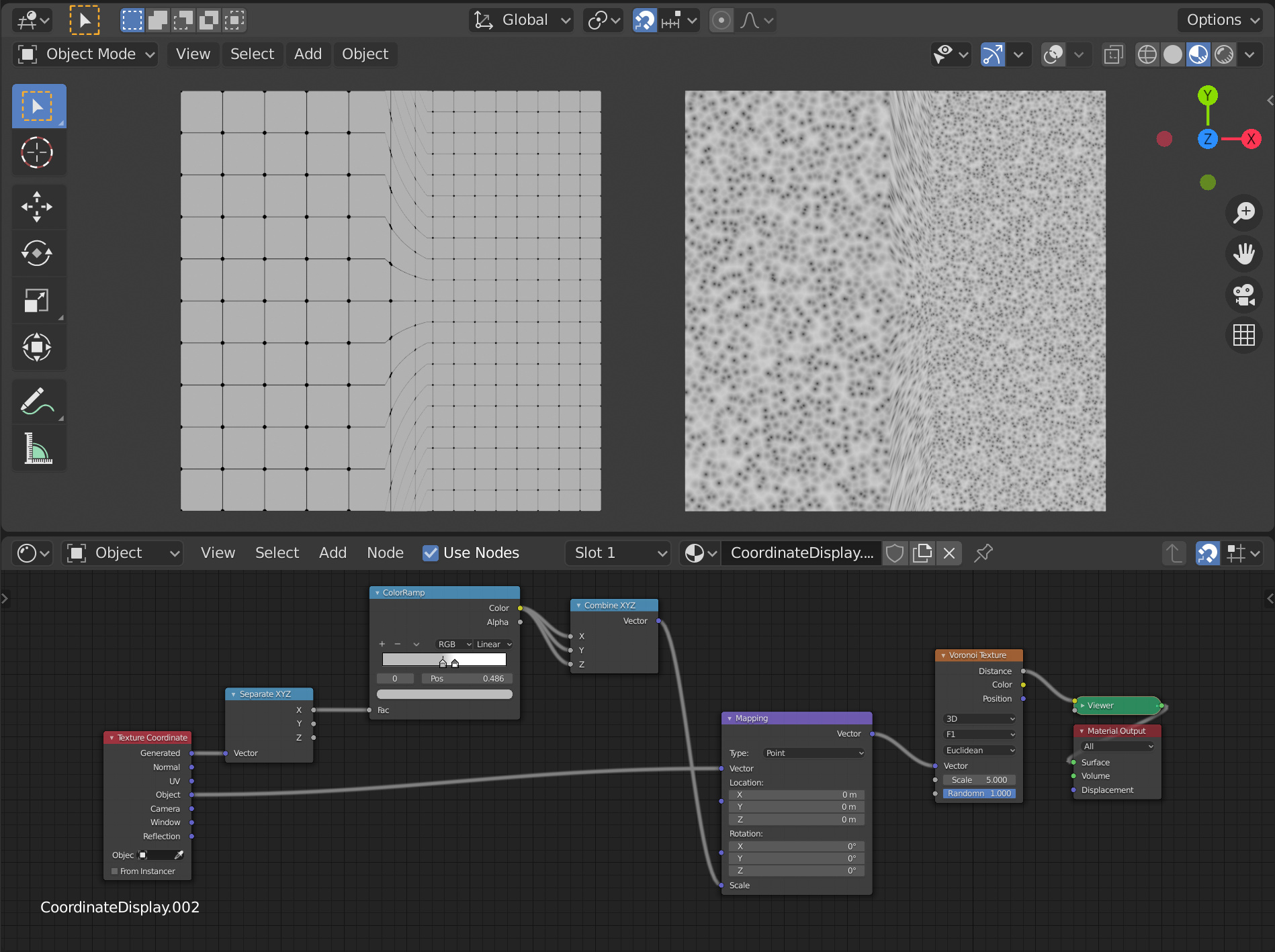
Take this as an example. With a constant cutoff, the voronoi scale on each side of the gradient is as expected and the voronoi cells are uniform in shape.
However if you change the gradient to something else so that there is a smooth transition between the two grey scales, the voronoi texture becomes distorted in the transition portion of the gradient.
It’s like they scale is only being properly applied in one direction (in this case, the vertical) whilst the horizontal scale seems to be immediately adopting the final (left hand) value immediately upon entering the transition phase of the gradient.
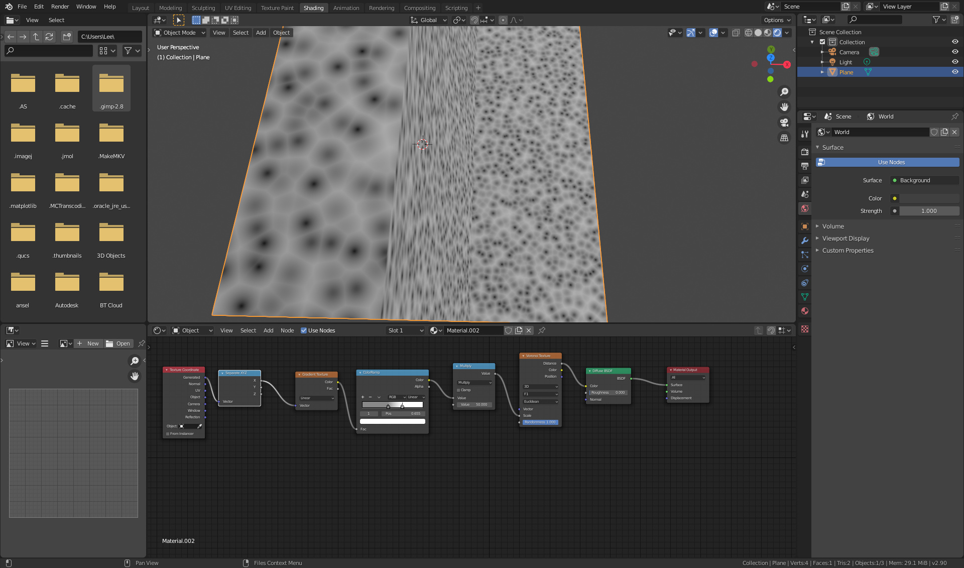
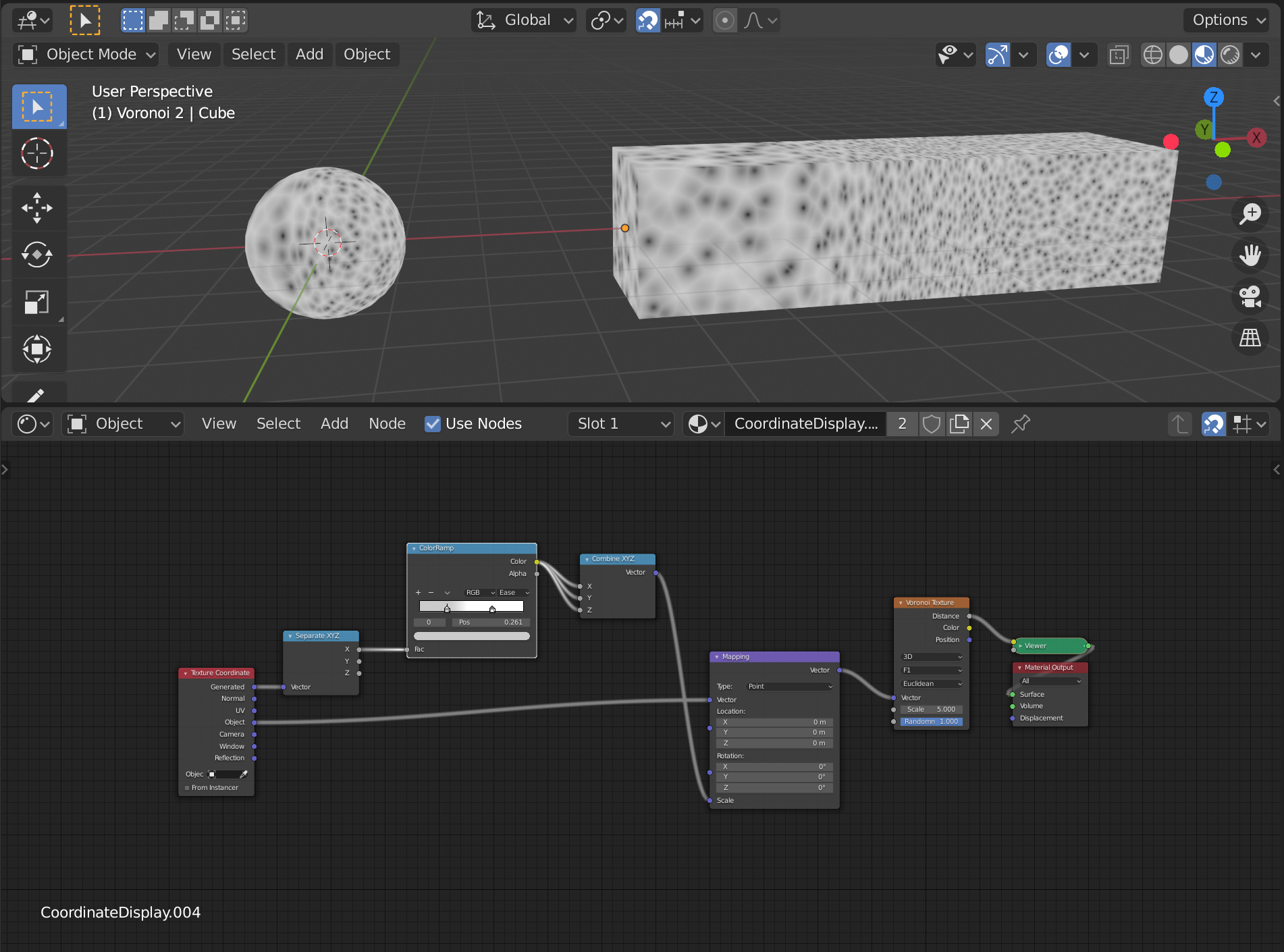
This is a similar effect but on a plane. Notice how going from left to right only vertical dimension of the cells seem to change with the gradient (as we would expect), whilst the horizontal scale seems immediately adopt the final small scale from the start of the gradient until the final size of the cells is attained at the end of the gradient.
Presumably because the voronoi texture is 3d, the voronoi cells should be able to be scaled independently in the X, Y or Z direction.
Could it be that because we only have one input for scale, that during the gradient transition this is only being applied to say X, whilst the Y and Z scales are immediately adopting the final value of the gradient.
I don’t think this is a bug, but rather the way the scaling works. The Scale slider in the node does the same thing a mapping node would do: it transforms the entire coordinate space the texture is evaluated on using the texture coordinate origin as a center of the scaling. In your screenshots it’s the lower corner of the plane, in the image below it’s the center of the plane, as it’s using the object coordinates.
Around the origin there is an area, where this kind of scaling is usable but as you get far away from the origin compared to the distance (width) the scaling occurs, as you can see on the top and bottom edges, the stretching starts to be much more noticeable since the absolute position change for each point in space due to the scaling increases with the distance from the origin.
In practice that means the area over wich the scaling occurs needs to be pretty wide compared to the objects dimensions and you can’t go too overboard with it, without creating too obvious stretching.
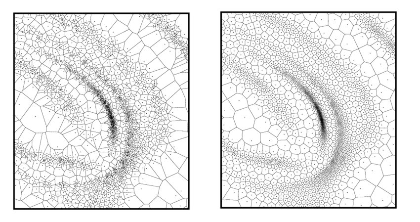
What we would need to create the desired effect, is a point density input that allowed us to change the density of the points the voronoi pattern is based on. Then we could get stuff like this (Source):
I was able to achieve most of what you guys are posting here. Unfortunately these results are far from acceptable levels for me. After some research the only solution for now seems to be the OSL. I’m marking Tarby’s post as a solution.
I have couple additional ideas that might be interesting regarding voronoi and median axis transform (of which I was recently educated about) But these topics are way above my coding ability, at least for now.
As I explained in a recent post, Blender’s Voronoi is really a ‘Worley’ Texture! And the cool thing about the ‘Worley’ algorithm is that it’s super fast, mainly because it uses a fixed point density, it doesn’t require to look up through points lists, and it’s easy to parallelize its computation.
What you guys are looking for here, it’s something else (not much related to the Worley’s noise). And that is also a difficult thing to acomplish for a couple of reasons:
First, how cell points are generated… Do we start from a highly dense grid and eliminate points based on some factor? Do we start with a coarse grid and refine it (as in the OSL code I wrote in the linked solution)? Do we use an offline generator (something like a poisson distribution with variable radius)?
Second, how the shader accesses the point data… Do we loop through all points in the list for every sample, with hundred of samples per pixel? How could we partition the point data to minimize having to look for all points? Perhaps using OpenVDB, but it will still be a far slower than worley’s.
Third, how to use other procedurals for controlling point density in realtime? It’s possible to do it offline!.. But could you imagine having to rebuild your point data everytime you do some change in your ‘density textures’?
@silex: appart from my OSL solution (which is pretty basic), there’s something that can be done. And that is to stack multiple voronoi nodes with different sizes, and scale/shift their minimum distances. It’s not perfect, but doable…
Thank you for your insight. I have an ignorant question for you regarding your second point.
Does currenty implemented Worley’s algorithm knows which point is mapped to a surface? I know that it is performing check within 3x3 kernel, but is the calculation performed for the whole domain or only for the parts that are projected onto the mesh?
Currently, the calculation is based on hashing the coordinates of each grid cell.
Here’s a short step by step:
Let’s say we want to sample the point (4.15, 5.65, 7.89) (with the coordinates already scaled by the ‘scale’ factor). That point belongs to the cell grid (4, 5, 7), (floor(x), floor(y), floor(z)). If we hash those coordinates we can produce a pseudo random coordinate xyz that has its components in the range [0, 1[, and if we add this new coordinate to the cell grid’s origin, we get the point in that cell. Then we just calculate the distance from our sampling point to the cell point and store it. We repeat the process for all neighbouring cells, and pick the lowest distance to each point.
Since hashing produces the same output for a specific input, every time a sample needs to calculate the cell point for (4,5,7) it will get the same random coordinate. So there’s no need to store anything, and avoid memory lookups (that are quite expensive in GPUs).
Boy, that’s really efficient design. Now I see why it is so hard to beat it in terms of performance.
And just for the sake of brainstorming, since I’m a theoretician right now:
Then, how about not touching point data at all? Just leave Worleys solution to random distribution of final points intact, and same goes for proximity check at the end.
But dynamically change kernel size and placement istead. The kernel data would needed to be stored and calculated, but it could take much less time than calculation of all points. And the caches for it could be relatively small.
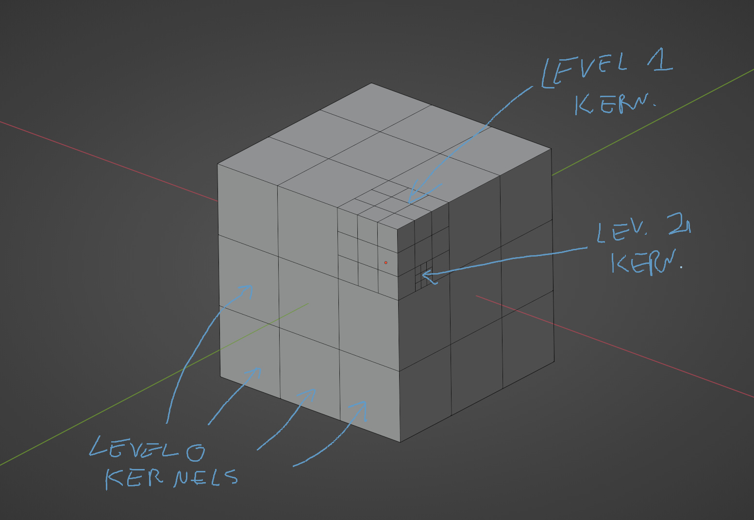
The simplest idea is to divide kernel space not only in grid, but recursive levels:
The hardest part I assume would be implementing cross-checking between kernels of various sizes.
The kernel space data could be calculated on the basis of vertex weight or vertex color. Since verts have xyz coordinates it could be translated to kernel grid easily. And the weight/col value could determine the kernel level (size).
You should try it with OSL to see if it works… But I suspect that dealing with samples that have Level0 but with neighbours with higher levels might be a bit tricky (not to mention that breaks parallelism a bit).
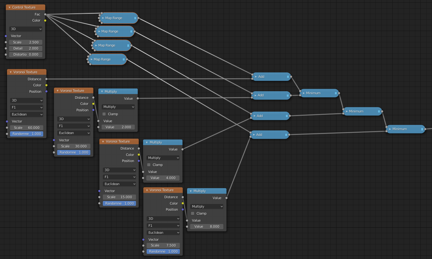
The nodetree i posted above is a bit similar to this, with 4 levels of detail…
Basically the algorithm stays the same but is executed 4 times with different scales.
Just out of curiosity - what map ranges did you use on the node setup?
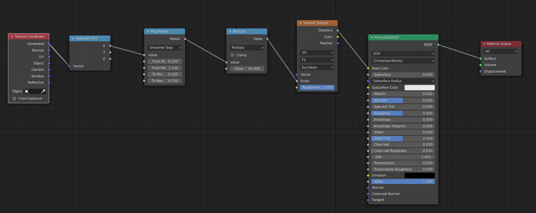
I’m playing with it right now, and the most interesting effect is when you multiply the voronoi distance by negative values.
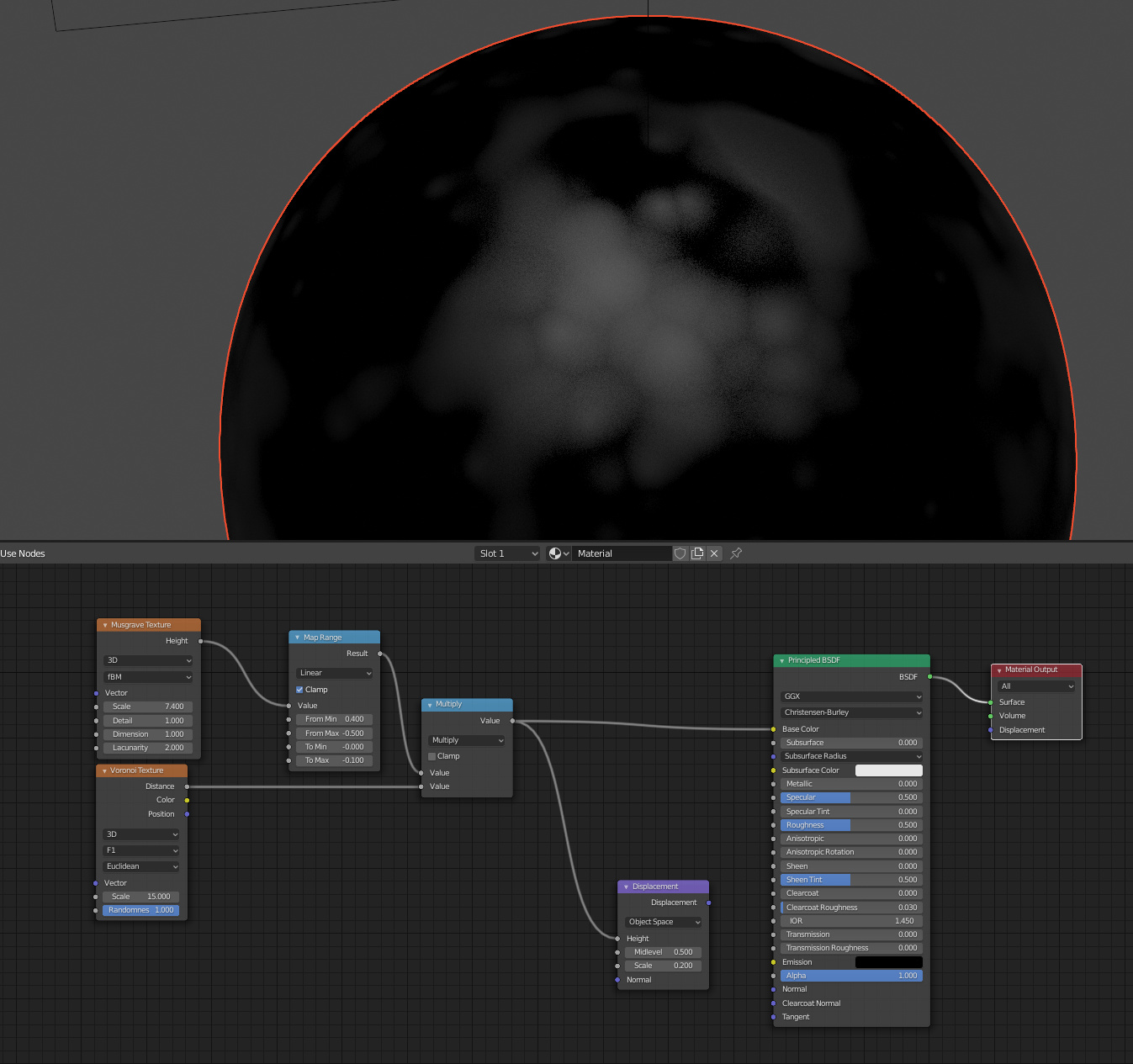
Below is roughly the effect I’m after. Think natural moss growing patterns. But right now it’s unusable - this pattern is only working when direcly connected as base color in Principled BSDF. In any other node it gives pure black due to negative value.
Both texture scaling and detail works like a charm. Using it as displacement gives trash thou.
Each one converts a fraction of the input to the [0,1] interval.
Something like → from[min:0.6, max:0.7] to [min:0.0, max:1.0].
In that case I used the following intervals ([0.6-0.7], [0.5-0.6], [0.4-0.5] and [0.3-0.4])…
Thought these values might vary depending the ‘Control Texture’ ranges (the Noise texture has its values around 0.5, so the fractions are near that).
Also, my ‘Add nodes’ are clamping the values (we only need the distances that are in [0, 1]). So I wouldn’t expect any results while multiplying with negative values.
In you case, I’m not figuring why you get that result (no blender atm)… I might need to check the source code from the MapRange node to see what it does when clamping a negative output (it should be clamped to 0, theoretically).