Thought it would be a cool idea to log and share some of the little useful tips and tricks I’ve learned through my experience with Geometry Nodes, both for my own purposes, and for other people. I originally started posting them in the geometry nodes development thread, but they really belong in their own topic. Plus, it will be easier to search the page for specific recipes.
These “recipes” should not be long enough for a tutorial, but should have significant value and an applicable use-case. For instance, rather than a post on “how to make a flower”, there should be a post on “phyllotaxis pattern”, and a seperate post on “petal modeling”.
Also, as much as I like experimental versions, I’m going to stick to stable releases. I want to keep my cookbook as relevant as possible, and having things go out of date next week is not the best way to go about this.
Some things will be simpler than others. Some things will be geared toward beginners, and some things will be targeted towards advanced users. I hope everyone learns something useful!
Comments, questions and discussion are all welcome on this thread, but if you’d like to post a recipe yourself, please PM me first so I can make sure it follows format. Thanks.
Recipe List:
22 Likes
Removing Volume to Mesh Artifacts
Using the accumulate field node with the island index, you can pick all mesh islands that are under a certain total face area.
This can be useful for removing artifacts from voxel-based effects, such as remesh or volume to mesh.
8 Likes
Distributing Points On Splines
To randomly distribute points along a spline, use the sample curve node with a random value. Resampling this curve first will give you control over the number of points. Make sure to set the sample curve node to factor, so it won’t depend on arbitrary spline lengths.
10 Likes
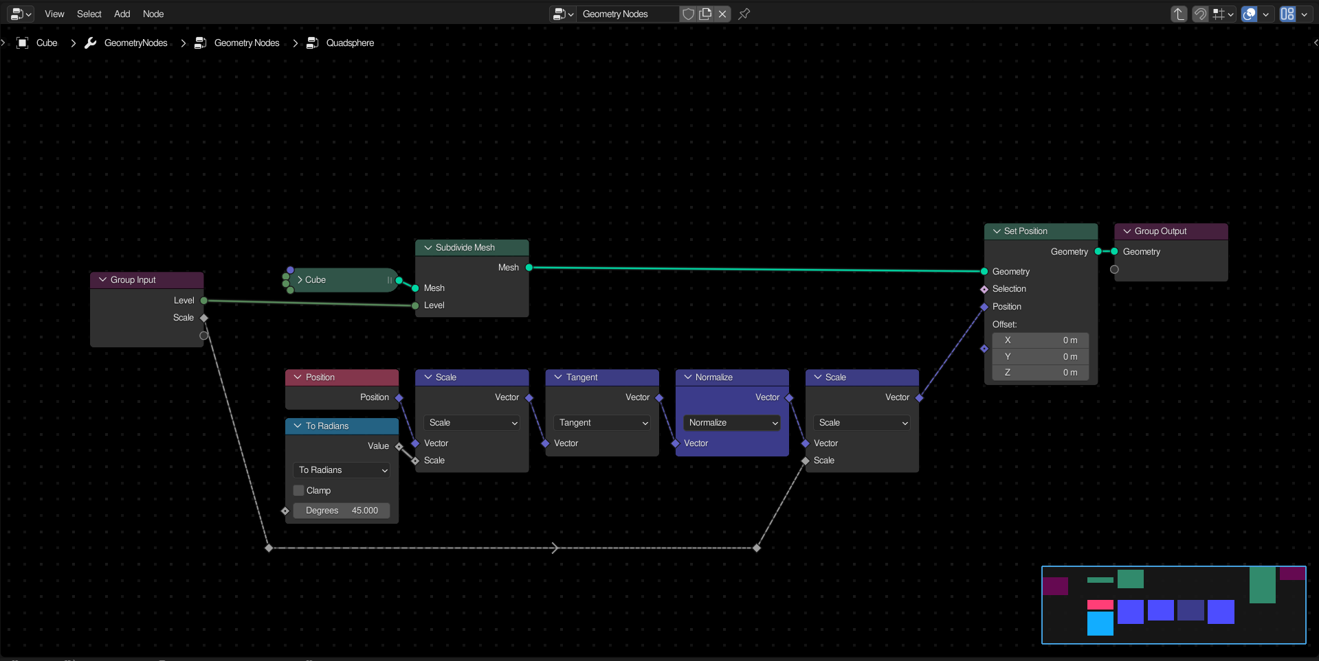
Quad-Sphere Primitive
Normalizing the position of a subdivided cube will map everything from a scale of 0 to 1, resulting in a sphere. If you scale the original coordinates by 45 degrees, and than take the tangent of this vector, the vertices will be more evenly spaced, reducing distortion. Finally, scaling this sphere by a custom value will allow control over the radius.
10 Likes
Do you have an explanation for the math? Because I can’t understand the meaning of finding the tangent of position. What if you use catmull Clark subdivision and then normalise?
I’d really appreciate it if some other community members could do youtube videos breaking down some of the math and if the posts in here could include an attached .blend file with the node group.
This is what tan(x*s) looks like (for s=1, showing the bit around x=0):
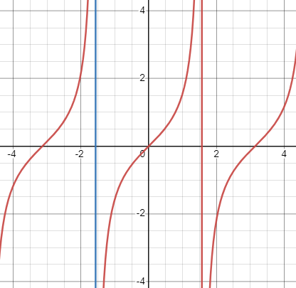
… where s is some scaling factor. The blue and red vertical lines are for x=-pi/2 and x=pi/2.
You can intuit from the shape of the function, that what mapping it is doing:
- not much for small values close to 0,
- pushes values close to -pi/2 and pi/2 to infinity.
The overall effect on the points of the cube looks like this (for scaling factor of 2.5 to show exaggerated effect):
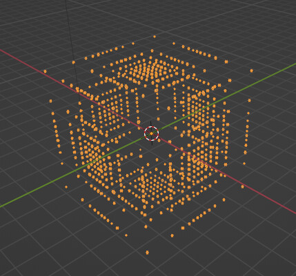
… so to answer your question, the tangent function is responsible for stretching out the bits of the cube that are the furthest away from the center, and squishes together the points that are closer to the center…
The normalization just makes everything spherical again.
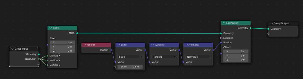
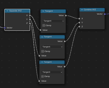
This is my setup - although, I use pi/2 as the scaling factor and not pi/4 as in the example as I think it looks better.
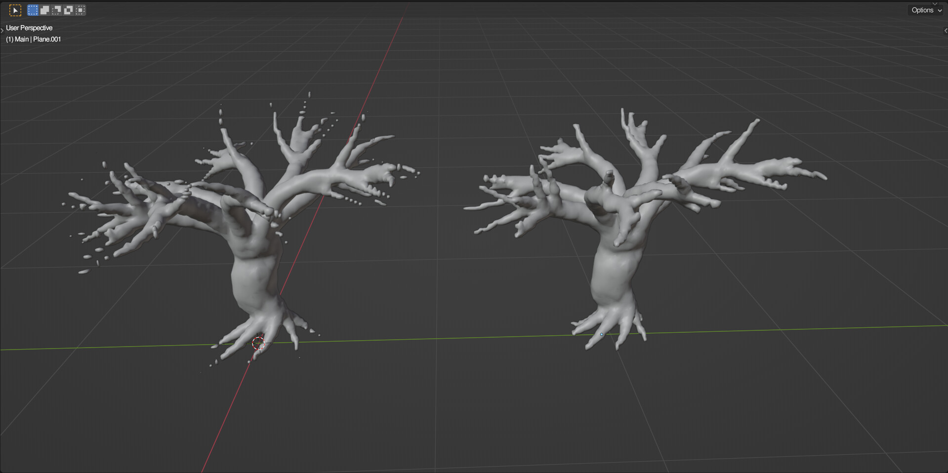
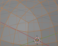
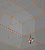
The reason why this method exists is because it has less stretching at the corners than the Catmull-Clark method, and you have better control over the resolution (not just powers of 2):
Catmull-Clark:
Tangent method:
Hope that helped.
11 Likes
Hey, thank you very much. I was going to explain it yesterday, but didn’t find the time. Your visualization is perfect.
Another thing to consider is that taking the tangent of position doesn’t make sense, except that the tangent node implicitly converts it to an angle vector first.
3 Likes
Thanks for the explanation. That does make sense. I did some math in Blender and calculated the standard deviation of the face area for each algorithm:
Normalised catmull clark- 0.005
Scale pi/4, tangent, normalise- 0.009
Scale pi/2, tangent, normalise- 0.002
Scale by 1.734, tangent, normalise- 0.0009
So as you can see, the last one is the mathematically best algorithm if you want equally sized faces. 1.734 is the best scaling factor because well…um…I don’t really know.
6 Likes
Yeah, I just did the same and came to that conclusion. I’m also pretty confused as to why it’s that number though…
2 Likes
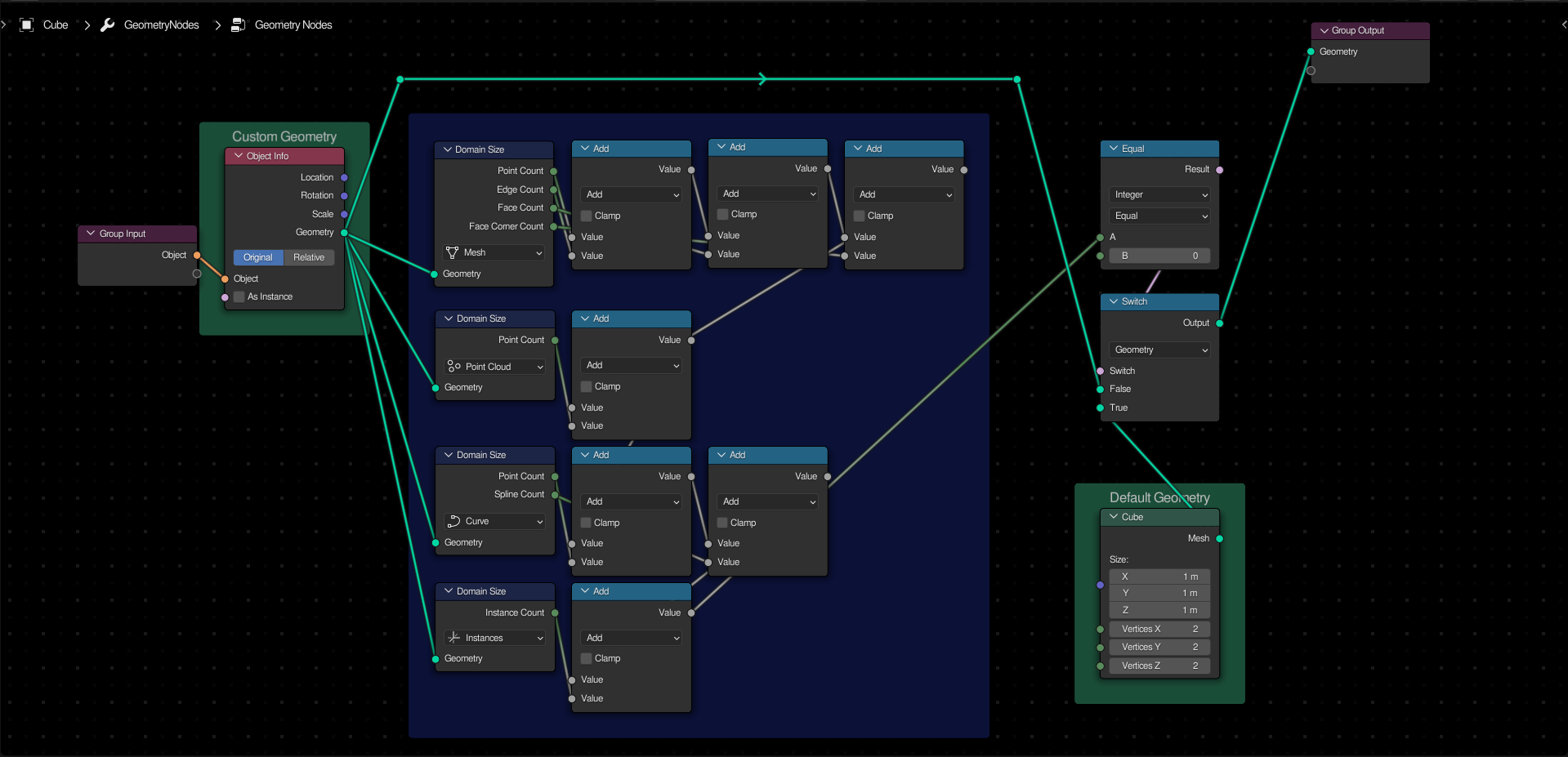
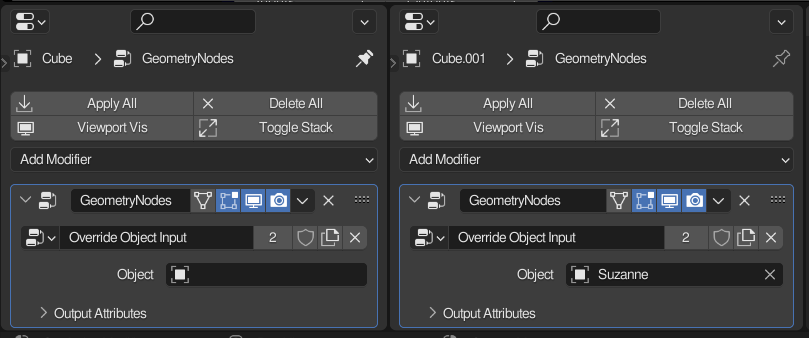
Override Object Input
The domain size node will output the count of each domain of a given type, in the input mesh. If all of the types are added together and compared against 0, you can detect if there is a valid object in the modifier (or nodegroup) input. Using this with a switch, it is possible to set a “default” geometry, and replace it with the input if applicable.
This is really useful if you want to have a blockout in gn, and replace everything with fancy assets from a collection when you are ready.
2 Likes
To drive across this point, this is basically what the Vector-Math Tangent looks like internally:
(… similar thing for Sine and Cosine)
Concerning your Override with Custom Object Input: Attribute Statistics in Point Domain mode covers all geometry types except instances. You can use that to simplify the network.
@Xeofrios - that scaling factor isn’t something I recognize but I’m sure there is a good reason for it to exist worth a 3Blue1Brown video. The nice thing about experimental math is that you don’t always need to to know exactly why something works to get it to work, and good work finding a better scaling factor.
We often talk about rotation in Radians and wondering if anyone needs a primer on Radians in Tips & Tricks? I think I have a way of explaining them without needing to mention Degrees.
2 Likes
I made a mistake - the initial cube I used has a “radius” of 0.5… If you start with a 2m cube then a scaling factor of pi/4 does seem to work best.
1 Like
Oh, good point. Faces, edges, and splines can’t exist without points, so there’s no reason to add them into the equation.
Adding together both points and instances should give a correct result.
1 Like
I wouldn’t call it convex, that would be the type of geometry that can be generated by a convex hull node. Spherical Polyhedron would a better word, ie a topology which can be morphed into a sphere. This tip can also be generalised to other topolgies, say if you want only surfaces geometry or only donuts, you can get their Euler characteristics too.
Speaking of the node tree, I think you can get rid of the capture attributes and set the value to 1 in the accumulate field.
2 Likes
Oh, I see. Such a setup could be useful for other things, but simply knowing the Euler characteristic isn’t enough to tell if a mesh is closed. A torus (or anything with a number of topological holes) will return a different result.
An actual solution to finding islands that are properly closed would be to find if the mesh island has any boundary edges… I will add that to the list soon.
(I will also delete the post to get rid of the misinformation. I may repost it with a correct description later. )
I guess you are right, a torus and a plane with a hole have the same euler characteristic.
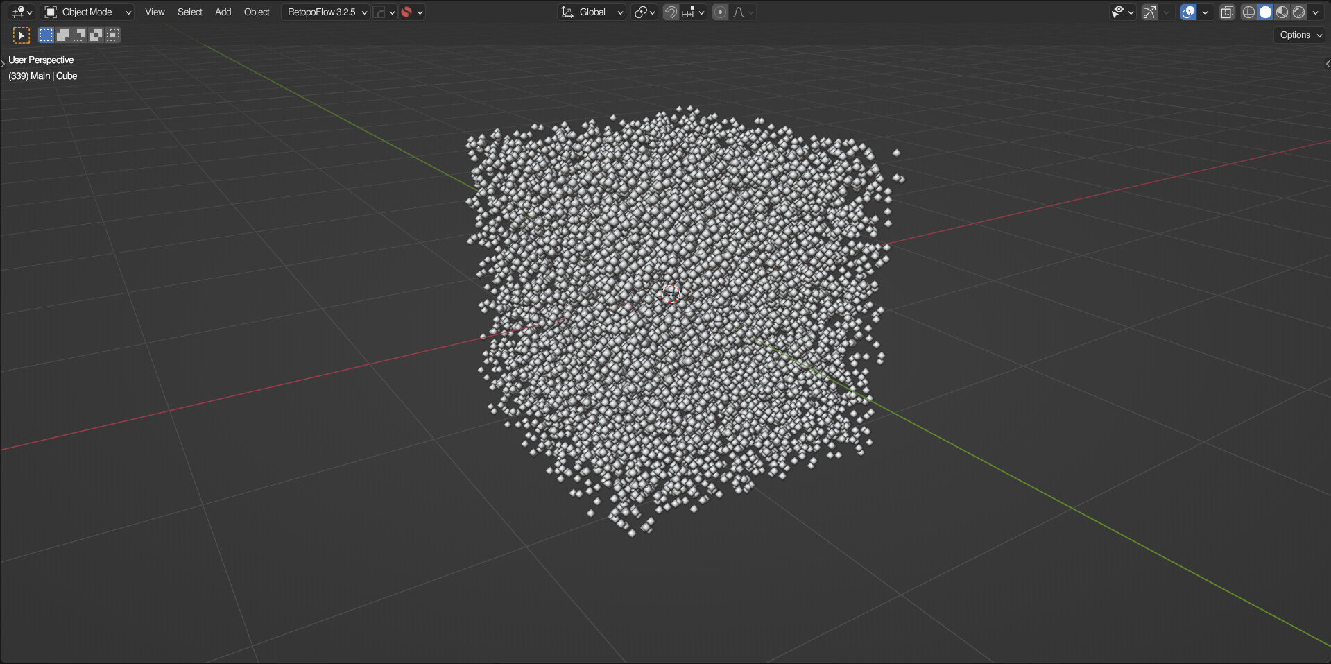
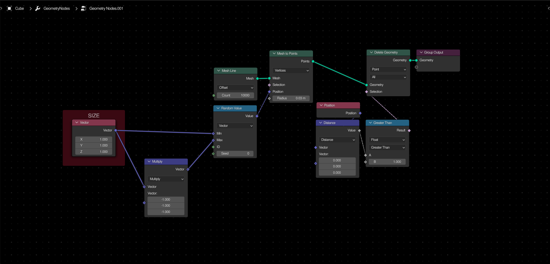
Point Cube Primitive
To create a custom primitive for distributing points in the shape of a cube, take a mesh line and convert it to a point cloud. Use a random vector to set the position of these points.
3 Likes
Point Sphere Primitive
To create a custom primitive for distributing points in the shape of a sphere, first create a
point cube, and then delete all points that are greater than a certain distance from the center.
2 Likes